Can a Belt-Driven Module Be Mounted Vertically? Vertical Load Calculation
Yes — a belt-driven linear module can be mounted vertically, and in lifting, stacking, and pick-and-place gantries it is often the most cost-effective way to get a fast Z axis. But belt module vertical mounting changes the load math completely: gravity stops being a friction coefficient and becomes a constant force your motor must fight on every stroke, and hold when the power is off. This guide walks through the vertical load calculation step by step, with a fully worked example, and covers the three design points that decide whether a vertical belt axis runs for years or fails in months.
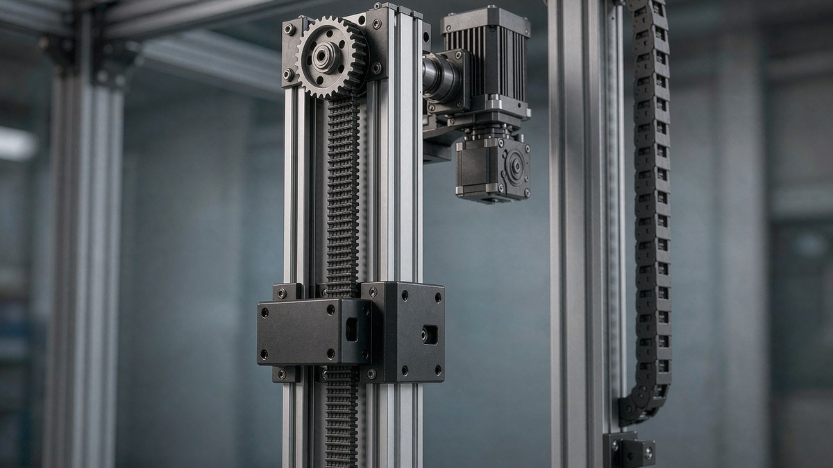
Illustration (AI-generated, not an actual product photo) — a belt-driven module in vertical orientation: the toothed belt runs the full height of the rail, the drive pulley and servo sit at the top, and the carriage works against gravity on every up stroke.
1. The Short Answer: Yes, If You Check Three Things
A timing belt module works vertically when all three of these are true:
- The motor can lift the load with margin — vertical load calculation shows enough torque at your target speed, with the gearbox efficiency included.
- The load cannot fall when power is off — you have a brake motor, a counterweight, or a mechanical lock. A belt axis back-drives freely; nothing holds the carriage by itself.
- The belt's allowable tensile force covers the static hanging load plus acceleration, with a safety factor of at least 2.
If any of the three fails, a vertical belt axis is the wrong choice — jump to section 5 for the alternatives.
2. How Gravity Changes the Load Calculation
On a horizontal axis, the motor fights friction and inertia:
F_horizontal = μ × m × g + m × a
With typical linear guide friction (μ ≈ 0.01–0.05), a 25 kg load needs only a few newtons to keep moving — acceleration dominates.
On a vertical axis, the friction term disappears into the noise and gravity takes over:
F_vertical = m × g + m × a
That 25 kg load now puts 245 N of constant force on the belt before it even starts moving. The corresponding continuous torque at the drive pulley is:
T = F × r ÷ η
where r is the pulley's pitch radius and η is the drivetrain efficiency (≈ 0.85–0.9 for a belt stage, lower with a reducer). This torque is not a peak — the motor must produce it continuously whenever the axis holds position or moves upward.
3. Worked Example: 25 kg Vertical Axis, 0.5 m/s
Take a typical lifting application: carriage + payload 25 kg, target speed 0.5 m/s, acceleration 2 m/s², drive pulley 20 teeth on a 5 mm-pitch belt (pitch diameter ≈ 31.8 mm, lead 100 mm/rev — see our belt module lead calculation guide).
Step 1 — Force: F = m(g + a) = 25 × (9.81 + 2) ≈ 295 N during upward acceleration; 245 N at constant speed and while holding.
Step 2 — Torque at the pulley: T = F × r ÷ η = 295 × 0.0159 ÷ 0.9 ≈ 5.2 N·m during acceleration; 4.3 N·m continuous while holding.
Step 3 — Motor speed: 0.5 m/s ÷ 0.1 m/rev = 5 rev/s = 300 rpm. A servo sized for ~5 N·m at 300 rpm with a 2× margin (≈ 10 N·m peak, ≥ 1.3 kW class, or a 5:1 reducer on a 400 W servo) covers this comfortably. A stepper at 300 rpm has already lost much of its torque curve — check the pull-out torque at speed, not the holding torque on the datasheet cover.
Step 4 — Belt check: the belt must carry 295 N plus dynamic shock. With a safety factor of 2, specify a belt whose allowable tensile force is ≥ 600 N — a standard 25 mm-wide 5M or 8M belt clears this with room to spare. The belt is rarely the weak point vertically; the motor's holding capability is.
4. Three Design Points That Decide Reliability
4.1 Holding the load at power-off
A belt-driven axis back-drives with very little resistance — cut the power and the load falls. You have three options, in order of preference:
- Brake motor (spring-applied, power-released) — the default answer. The brake holds the load the instant power drops. Size the brake for the static torque (2.4 N·m in our example) with the same 2× margin, and remember the brake is for holding, not emergency stopping at speed.
- Counterweight or gas spring — cancels most of m × g mechanically, shrinking the motor to an acceleration-only size. Worth it for heavy loads or high duty cycles; it also halves the heat in the motor.
- Self-locking element — a worm reducer in the drivetrain. Effective but costs 30–50% efficiency and cannot be back-driven for manual adjustment.
4.2 Belt tension and mounting direction
Vertically, the belt carries the hanging load 24/7, so pre-tension creeps faster than in horizontal duty. Put the drive pulley at the top where possible — the loaded belt span then runs straight from carriage to pulley without passing through the idler, and the idler side stays unloaded. Re-check tension at the first 500 hours, then at normal service intervals.
4.3 Feedback and fault behavior
If the belt ever jumps a tooth on a horizontal axis, you lose position but nobody gets hurt. Vertically, a tooth jump is a falling load. A vertical axis deserves an encoder on the carriage side (linear scale) or at minimum a brake plus mechanical end-stops with energy-absorbing bumpers at the bottom. For personnel-adjacent equipment, add a safety-rated brake or rail clamp regardless of calculations.
5. When a Vertical Belt Module Is the Wrong Choice
Be honest with the physics — a belt module vertically is a fast, economical Z axis, but not a universal one:
- Loads above roughly 50–80 kg — continuous holding torque pushes you into large motors; a ball screw with its self-locking tendency (or a counterbalanced screw axis) is usually cheaper.
- Micron-level Z positioning — belt elasticity shows up directly in vertical repeatability under load; a ground ball screw wins below about ±0.02 mm.
- Long idle holding under full load — a motor holding torque for hours runs hot; a screw axis or a counterweight removes the problem at the source.
Inside its envelope — light-to-medium loads, fast strokes, moderate accuracy — the vertical belt axis is hard to beat on speed and cost. Our ZW series synchronous belt silent modules cover strokes to 4 m in vertical gantries, and the fully enclosed belt module adds protection for dusty or chip-filled environments where an open belt would degrade quickly.
Related reading:
- How to Calculate Belt Module Lead: Formulas & Worked Examples
- How to Select a Belt-Driven Linear Module: Stroke, Load & Accuracy
- Linear Motion for Vision Inspection Machines: Why Belt + Rack-and-Pinion Is the Winning Combo
📄 Free downloads: ZB Robot Product Catalog (full ZW series selection tables) | CE Certification
Planning a vertical axis? Send us your load, stroke, and cycle time via the contact page or email zhaohaijun@zenbotsmart.com — for non-standard vertical conditions (odd strokes, special motor interfaces, protective enclosures) we return a complete sizing sheet and a written custom-build timeline, so you know the delivery date before you commit.