If you design vision inspection machines, you've probably faced this puzzle: the conveying axis runs over a meter, the lifting axis moves just a few hundred millimeters, and each axis has different speed, load, and precision demands. Which linear module goes where — without overspending or underspecifying?
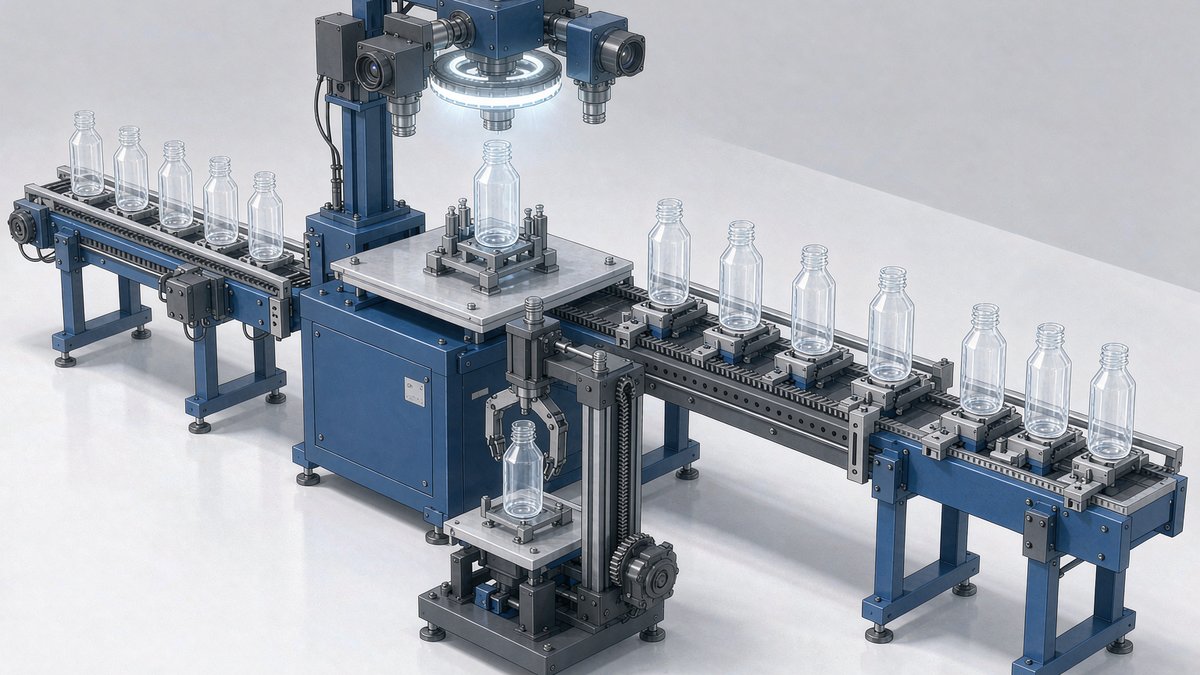
We recently supplied a complete linear motion package for a Chinese manufacturer of preform inspection machines (machines rated for 48,000 parts/hour). Here is the full breakdown of that belt-driven + rack-and-pinion combo: why long travel gets a belt module, why the vertical axis gets a rack — and the three mistakes that cost machine builders the most rework time.
The Two Axes That Matter
The motion section of this machine is simple — two axes:
| Axis | Function | Solution | Stroke | Key components |
|---|---|---|---|---|
| X (horizontal transfer) | Move preforms into the inspection station | Belt-driven module | 1200mm | 8M AT-type timing belt + planetary gearbox + 6 sliders |
| Z (vertical lift) | Raise/lower camera & gripper | Rack-and-pinion module | 300mm | Helical rack drive + 90° bevel gearbox + 4 sliders |
Why the Long Axis Gets a Belt-Driven Module
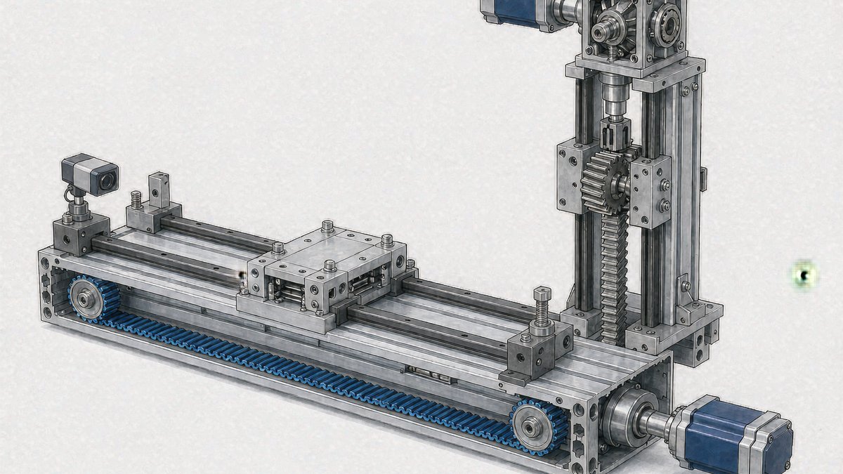
Strip a belt-driven linear module down and you find four things: a motor + gearbox driving a pulley, a timing belt that moves the carriage, guide rails for direction, and photoelectric sensors for positioning. No ball screw, no gear mesh — which makes it the natural choice for "fast and far":
- Flexible stroke. The 1200mm X-axis here is built from two 600mm base sections joined with dowel-pinned splices. Single-piece bases that long are expensive to ship and often won't fit through a standard elevator; a properly pinned splice gives up nothing in accuracy.
- Speed. Belt modules routinely run 1–2 m/s — several times faster than ball-screw units (typically under 0.5 m/s). High-throughput inspection lines can't live without it.
- Lower cost at long stroke. At equal stroke, belt systems run 20–40% cheaper than ball screws, with no critical-speed or screw-droop issues to engineer around.
Note the six sliders on the X-axis — three times the usual count. The gripper and product weight all ride on that carriage; more sliders share the load, which means less deflection and longer rail life.
Why the Lifting Axis Gets a Rack-and-Pinion Module
For a 300mm vertical stroke, why not a belt — or a ball screw?
- No ratcheting under gravity. Belt drives rely on tooth engagement; under constant vertical load they carry a skip-tooth risk. A rack-and-pinion is a hard mesh, and paired with a brake motor it holds position even on power loss.
- Accuracy where it counts. Helical gears mesh with high contact ratio and minimal backlash, delivering sub-millimeter repeatability for station positioning — with far less long-term wear than straight-cut spur gears.
- The 90° bevel gearbox is the quiet win. Instead of a motor sticking straight up from the top of the module, a right-angle planetary gearbox lays the motor horizontally. On an inspection machine, that saved height is where the camera, lighting, and service access all live.
Selection Table (Steal This)
| Condition | Recommended solution | Typical application |
|---|---|---|
| Stroke >800mm, horizontal, speed priority | Belt-driven module | Conveying, loading/unloading, long transfers |
| Stroke <500mm, vertical, holding required | Rack-and-pinion + brake motor | Lift axes, Z-axis positioning |
| Stroke <1m, accuracy ≤±0.02mm | Ball screw module | Precision dispensing, fastening |
| Stroke >2m or heavy loads | Rack-and-pinion + oversized rails | Gantry systems, heavy frames |
| Vertical axis with tight headroom | Rack-and-pinion + 90° gearbox | Inspection machines, filling machines |
Three Mistakes That Cost Real Money
- Splices without dowel pins. Bolt-only splices creep. Six months in, the joint shifts a few hundredths of a millimeter, sliders clunk across the seam, and your camera images blur. Pinned + ground splices are non-negotiable.
- Photoelectric limit switches with no mechanical backup. Dust kills optical sensors. When one fails mid-cycle, the carriage slams into the end stop. Every axis in this build carries both external photo sensors and mechanical stop blocks — tens of dollars of insurance against a week of crash repairs.
- Specifying a belt on a vertical axis to save budget — and watching the camera free-fall on power loss. Holding requirements must be settled at selection time: rack-and-pinion with brake motor, or belt with a brake. Never bare.
Bottom Line
Specifying linear motion for a vision inspection machine comes down to one sentence: let the belt module own horizontal speed, let the rack-and-pinion own vertical holding. This combo is proven at 48,000-parts-per-hour throughput and transfers directly to cap inspection, part feeding, rejection, and palletizing cells.
Specifying a machine of your own? Download our product catalog for full specifications on belt-driven modules, rack-and-pinion modules, and linear guides — or contact us with your stroke, load, and cycle time, and we'll send back a configured proposal.
Further reading: - Belt vs. Ball Screw: How to Choose a Linear Module - Rack-and-Pinion Modules for Long-Stroke Applications