How to Select a Belt-Driven Linear Module: Stroke, Load & Accuracy Explained
When it comes to belt-driven linear module selection, many buyers start with "How much does it cost?" — but price comes last. Until three parameters are nailed down — stroke, load, and accuracy — any quotation is just a guess. This guide walks through each parameter with the formulas you actually need, plus a one-page checklist you can fill in and send to any linear module manufacturer to get a correct spec on the first pass.
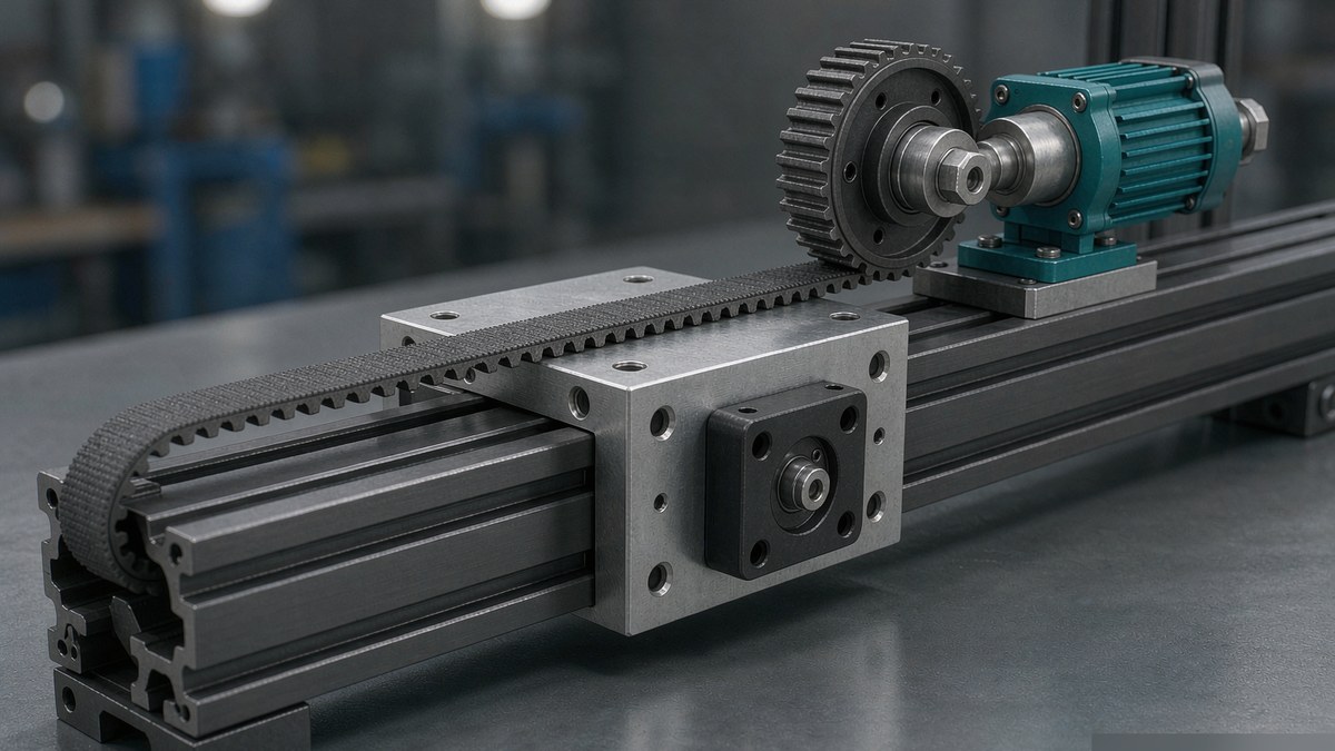
1. Stroke: Calculate the Effective Stroke, Then Add Safety Margins
Stroke is the first parameter to fix because it determines the base length — and a big share of the cost.
The formula is simple: Effective stroke = actual travel distance + safety margins at both ends.
- Actual travel distance: center-to-center distance between pick and place positions, from your process layout.
- Safety margin: 20–50 mm at each end. Belt modules rely on photo sensors or limit switches; too little margin risks crashing the limit, too much makes the base longer than needed and reduces rigidity.
Belt-driven modules shine in medium-to-long strokes: 100–4000 mm is a common range. Beyond 2 meters, the cost advantage over ball screws becomes dramatic — a long ball screw hits critical-speed limits and needs a larger diameter or intermediate supports. Rule of thumb: over 1500 mm, go belt; under 300 mm with high precision, go ball screw.
2. Load: How to Calculate Belt Module Load Capacity
Load is where most selection mistakes happen. Here is how to calculate belt module load in three steps:
Step 1 — Total moving mass Moving mass = workpiece + fixture + everything mounted on the carriage. Don't forget the cable drag chain's share — on long strokes it can add several kilograms.
Step 2 — Required thrust For horizontal mounting, thrust overcomes friction and acceleration: F = μ·m·g + m·a Use μ = 0.01–0.05 for rolling linear guides. Example: 20 kg load at 5 m/s² acceleration needs roughly 20×0.02×9.8 + 20×5 ≈ 104 N.
Step 3 — Check the belt's allowable tension A belt module's load limit is set by the belt's allowable tension, not motor torque. The "max load" in a catalog assumes a specific speed — the faster you run, the lower the allowable load. High speed combined with heavy load is where belt modules fail most often. Always check the load-versus-speed curve at your actual operating speed, never just the catalog maximum.
One more note: vertical mounting is a different game — gravity loads the belt continuously. Belt modules are generally not recommended as vertical axes; if you must, you'll need counterweights or a brake motor. We'll cover that in a dedicated article.
3. Accuracy: Repeatability vs. Absolute Positioning Accuracy
The third parameter is accuracy, and there's a common confusion here:
- Repeatability: the scatter when approaching the same commanded position repeatedly from the same direction. Belt modules typically deliver ±0.04–±0.05 mm; good ones reach ±0.02 mm. Most handling, loading/unloading, and dispensing applications actually depend on this number.
- Absolute positioning accuracy: command 1000 mm — how far did it actually travel? Affected by belt pitch error and thermal expansion, belt modules typically land in the 0.1–0.3 mm/m range.
So if your application is "stop at the same point every time" (assembly positioning), ±0.05 mm repeatability from a belt module is plenty. If it's "be accurate everywhere along the stroke" (inspection scanning), add a linear encoder — or choose a ball screw module instead.
4. Three Hidden Conditions Beyond the Big Three
Stroke, load, and accuracy settled? Don't order yet — confirm three more things:
- Operating speed: belt modules typically top out at 3–5 m/s, but speed trades off against load and service life. Derive it from your cycle time; don't run at the limit.
- Mounting orientation: horizontal, wall-mounted, or inverted — each has different lubrication and sealing requirements. Flag inverted mounting upfront.
- Environment: dust, coolant mist, or cleanroom conditions decide between semi-closed and fully enclosed designs. In dusty shops, go straight to a fully enclosed belt module — it saves a lot of maintenance later.
5. A One-Page Selection Checklist
| Item | Your Spec | Notes |
|---|---|---|
| Effective stroke | ____ mm | Travel distance + 20–50 mm each end |
| Total moving mass | ____ kg | Include fixture & drag chain share |
| Speed / acceleration | _ m/s / _ m/s² | Derived from cycle time |
| Repeatability required | ±____ mm | ±0.05 fine for handling; inspection needs more |
| Mounting orientation | Horizontal / side / inverted / vertical | Vertical needs separate review |
| Environment | Dust / oil mist / cleanroom | Semi-closed vs fully enclosed |
| Daily run time | ____ h | Affects life-margin sizing |
Fill this table in and selection is mostly done. ZB Robot is a custom (non-standard) module integration specialist: our ZW series silent belt-driven modules cover widths 40/45/50/60/80 mm and strokes from 100 to 4000 mm, with standard lead times of 7–15 days, MOQ 1, factory-direct from Suzhou. If any line of your checklist falls outside the standard envelope — extra-long stroke, vertical duty, special environment — we handle custom work too, and we put the full timeline in writing before you commit: how long a custom linear module takes and what happens at each step, no surprises.
Related reading: - Belt vs. Ball Screw Linear Modules: How to Choose by Stroke and Precision - Rack-and-Pinion vs Ball Screw for Long-Stroke Applications - Linear Guide Selection: Load, Precision & Mounting
📄 Free downloads: ZB Robot Product Catalog (full ZW series selection tables) | CE Certification
Not sure about a parameter? Fill in the checklist and reach us via the contact page or email zhaohaijun@zenbotsmart.com — an engineer replies with a selection proposal within one business day.