How to Calculate Belt Module Lead: Formulas & Worked Examples
If you are sizing a linear axis, belt module lead calculation is the step that connects your motor to your motion: get the lead right, and speed, resolution, and motor sizing all fall into place. Get it wrong, and you end up with an axis that can't reach its target speed — or a motor running at 50 rpm where it has no torque. This guide gives you the formulas that actually matter, two fully worked examples, and the three mistakes that cause most miscalculations in the field.
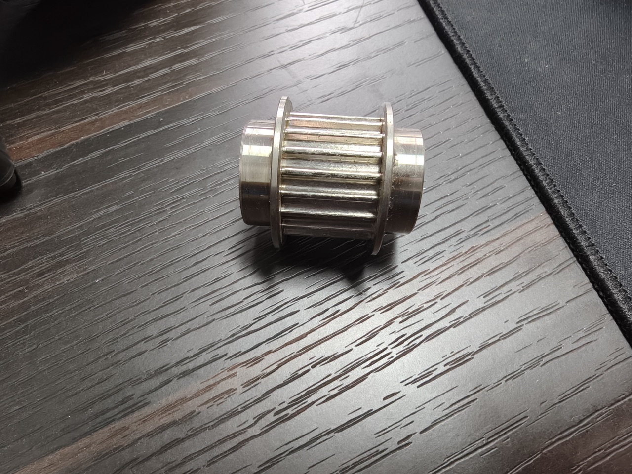
1. What "Lead" Means on a Belt-Driven Module
On a ball screw, lead is ground into the screw. On a belt module, lead is created by the drive pulley:
Lead = π × pitch diameter of the drive pulley
The pitch diameter is where the belt's pitch line sits — not the pulley's outer diameter. For a timing pulley, the pitch diameter comes straight from the tooth count and belt pitch:
Pitch diameter Dp = (tooth count Z × belt pitch p) ÷ π
Example: a 20-tooth pulley on a 5 mm-pitch belt gives Dp = 20 × 5 ÷ 3.14159 ≈ 31.83 mm, so the lead is π × 31.83 ≈ 100 mm per revolution. That round number is why 20-tooth / 5 mm-pitch combinations are so common on belt-driven linear modules.
2. The Three Formulas You Actually Use
Once you know the lead L (mm/rev), everything else is arithmetic:
- Linear speed: v (m/s) = L × n ÷ 60,000 — where n is motor speed in rpm. A 100 mm lead at 3,000 rpm gives 100 × 3,000 ÷ 60,000 = 5 m/s.
- Required motor speed: n (rpm) = 60,000 × v ÷ L. Need 2 m/s with a 100 mm lead? n = 60,000 × 2 ÷ 100 = 1,200 rpm — comfortably inside a servo motor's torque band.
- Position resolution: resolution (mm/pulse) = L ÷ encoder counts per rev ÷ multiplier. With a 100 mm lead and a 10,000-count encoder at 4× multiplication, each pulse is 100 ÷ 40,000 = 0.0025 mm — fine enough for any handling task.
If a gearbox sits between motor and pulley, divide: effective lead = pulley lead ÷ gear ratio. A 100 mm lead behind a 5:1 reducer behaves like a 20 mm lead — speed drops five-fold, thrust and resolution improve five-fold.
3. Worked Example A: From Cycle Time to Pulley Choice
A pick-and-place axis must move 1,800 mm in 1.2 s, with 0.3 s for acceleration and deceleration. Average speed is 1.5 m/s; peak speed works out to roughly 2 m/s.
- Target peak speed: v = 2 m/s.
- Motor sweet spot: a 400 W servo delivers its rated torque up to 3,000 rpm.
- Required lead: L = 60,000 × v ÷ n = 60,000 × 2 ÷ 3,000 = 40 mm/rev minimum.
- Pulley choice: a 100 mm lead (20-tooth, 5 mm pitch) runs the motor at just 1,200 rpm at peak — leaving headroom for a heavier load later. A 50 mm lead (10-tooth) would also work but pushes the motor to 2,400 rpm and halves the resolution.
Result: 20-tooth pulley, no gearbox, motor idling at 40% of its rated speed. That margin is free insurance.
4. Worked Example B: When the Numbers Say "Add a Reducer"
Same axis, but now the carriage carries 60 kg and must accelerate at 8 m/s². Required thrust F = μ·m·g + m·a ≈ 0.02 × 60 × 9.8 + 60 × 8 ≈ 492 N. With a 100 mm lead (radius 15.9 mm), motor torque needed = 492 × 0.0159 ≈ 7.8 N·m — beyond a 400 W servo's continuous rating.
Options: bigger motor, or a reducer. A 3:1 planetary reducer cuts effective lead to 33.3 mm, triples reflected torque, and keeps the motor at 3,600 rpm at the same 2 m/s — inside the continuous zone with margin. The trade-off is top speed: with the reducer, the axis caps out around 2.5 m/s instead of 7.5 m/s. For this duty cycle, that is the right exchange.
5. Three Mistakes That Cause Most Miscalculations
- Using outer diameter instead of pitch diameter. A "32 mm pulley" is not a 100 mm lead if you measure the flanges. Always compute from tooth count × belt pitch.
- Forgetting the reducer ratio. Nameplate speed is motor-side. Every formula above needs the effective lead after the gearbox.
- Checking speed but not resolution. A coarse lead with a low-count encoder can put your pulse resolution above the repeatability you promised. Verify mm/pulse before you commit.
Belt modules earn their keep in the 100–4,000 mm stroke range exactly because lead scales so cleanly: one pulley swap re-rates the whole axis. Our ZW series silent belt-driven modules ship with standardized pulley sets, and for dusty environments the fully enclosed belt module keeps the belt and pulley protected without changing the math.
6. Quick-Reference Calculation Table
| Quantity | Formula | Units |
|---|---|---|
| Pitch diameter | Dp = Z × p ÷ π | mm |
| Lead | L = π × Dp (= Z × p) | mm/rev |
| Linear speed | v = L × n ÷ 60,000 | m/s |
| Required rpm | n = 60,000 × v ÷ L | rpm |
| Effective lead (with reducer) | L_eff = L ÷ i | mm/rev |
| Resolution | L ÷ (encoder counts × multiplier) | mm/pulse |
ZB Robot is a custom (non-standard) module integration specialist: if your lead calculation lands between standard pulley sets — an odd speed target, a vertical axis, an unusual encoder — we size the pulley, motor, and reducer as one package and put the full custom timeline in writing before you commit.
Related reading:
- How to Select a Belt-Driven Linear Module: Stroke, Load & Accuracy
- Rack-and-Pinion vs Ball Screw for Long-Stroke Applications
- Linear Motion for Vision Inspection Machines: Why Belt + Rack-and-Pinion Is the Winning Combo
📄 Free downloads: ZB Robot Product Catalog (full ZW series selection tables) | CE Certification
Want us to check your numbers? Send your stroke, load, and cycle time via the contact page or email zhaohaijun@zenbotsmart.com — an engineer replies with a complete lead-and-motor sizing sheet within one business day.