Non-standard linear module integration, also called custom linear module integration, is the design-and-supply work of building a motion station for which no catalogue part fits as-is. Some stations on a seed processing and storage line look simple and are almost impossible to build from catalogue parts. This is one of them: moving cylindrical bins, seed boxes and returnable containers between stations on a fixed cycle, year after year, in a dusty processing hall.
What follows is a working record of one such station - a twin-Z truss gantry pick-and-place module built for a seed processing and reserve facility inside a national grain reserve system. It is not a product advertisement. It is a set of engineering decisions you can reuse: how to break down the duty, how to fix the configuration, how to allocate the error budget, how to schedule the job, and what documentation a state-owned customer actually checks.
Two notes before we start. First, this is a non-standard integration project. Our scope was the design and supply of the linear motion units; the machine was completed with an integrator. Second, the customer name is withheld as is normal industry and confidentiality practice. All figures described below are those that can be disclosed.
1\. Break down the duty before you ask for a model
The most common mistake in a project like this is opening the drawing and starting to search for a module. The correct order is to answer four questions first: what is the envelope, what is the payload, where is its centre of gravity, and how much movement is allowed at the workpiece. Until those four are fixed, any model selection is guesswork.
For this class of station, the duty decomposes like this.
The handled parts are cylindrical bins and seed boxes. Unit weight ranges from roughly ten to tens of kilograms, and the centre of gravity shifts with fill level - a genuinely variable-load duty.
The motion is a three-axis transfer between stations: a long horizontal shuttle, plus vertical lift to clear a transition height and a lower back down. The cycle time is set by line output, so the reciprocating move has to finish in seconds, and every stop has to land in the same place.
The environment is a grain and seed processing hall: dust, chaff, and periodic washdown. Guides and transmission parts need protection and the ability to survive being dirty.
The customer is a state-owned entity. Beyond functional acceptance, they review drawings, the bill of materials, inspection records and the delivery file set. In my experience this closes out projects more often than the technical specification does.
Once those five lines are written down, the real nature of the job becomes obvious. This is not an axis-selection problem. It is an integration problem for a three-axis transfer mechanism.
2\. Five decisions you can read straight off the model
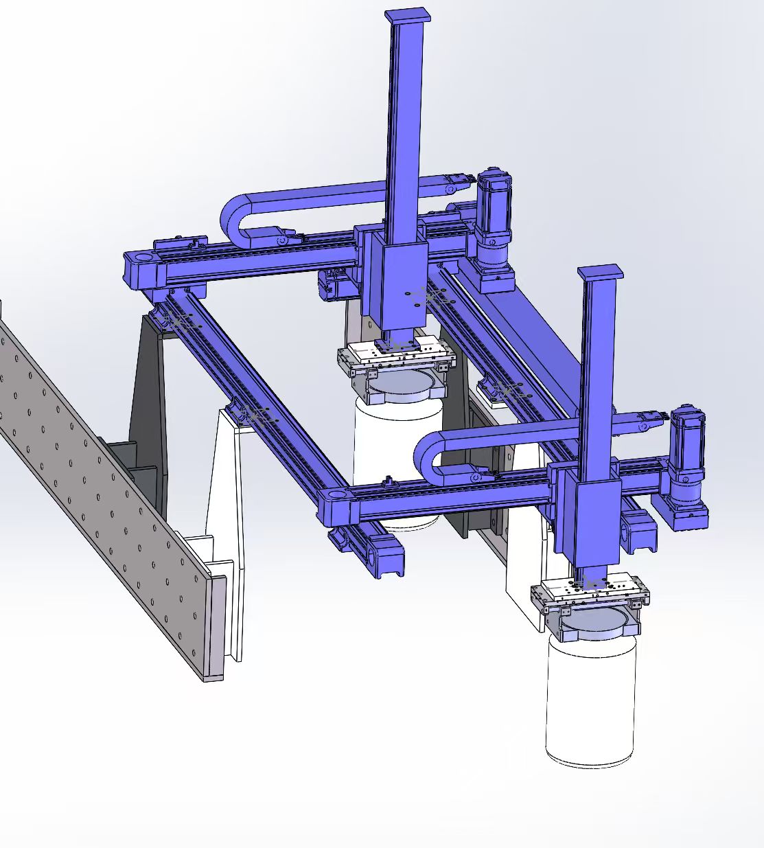
Once the CAD assembly exists, the scheme is largely written into it. Five decisions in this drawing drive everything else.
Truss crossbeam, not a solid beam. The beam uses chords plus web members. On a gantry spanning more than a metre, a solid beam gets heavy and loses section efficiency fast; a truss buys bending stiffness per kilogram. The price is that the node where web members meet the chord must be held tightly. If node fabrication is sloppy, the truss advantage is spent on joint deformation.
Twin columns, two independently driven Z axes. Two vertical columns each carry one Z axis, and the two must hold their relative position. Independent drives mean each axis can take a different load or sit at a different height at the same moment. The cost is that you now own a height-synchronisation problem between the two.
A defined vertical reference at the workpiece. Under each carriage sits a round tray structure carrying the cylindrical container. That tray is a high-stiffness part. It has to stay flat under rated load, otherwise the container rocks and the repeatability of the whole pick is gone. Many integrators draw the tray as an accessory, then discover that the real accuracy killer is a steel plate weighing a few tens of kilograms.
Motor at the end of travel, drag chain in line with the axis. The modules on the beam place the motor at the end of the run so the full stroke stays usable, and the drag chain runs parallel to the axis so it adds less side load to the moving axis.
The mounting plate and brace on the left are part of the scheme. You can see a drilled mounting plate and a triangular support. That tells you the structure has to interface with an existing platform or conveyor, and that interface is what sets the installation datum for the entire frame.
3\. Belt or ball screw for this duty
This is the most common question in non-standard integration. The answer turns on cycle time, accuracy requirement and environment.
Belt-driven modules win on cycle time and maintenance. Higher speeds and faster acceleration suit high-frequency pick-and-place. Efficiency is high and self-heating is low. Belt breakage is an abnormal condition, not a normal one. The structure is simple and spare parts are generic, which shortens the maintenance window. For a line that runs continuously, those three points matter.
Ball screw modules win on accuracy retention and self-locking. Belt tension decays over time and needs periodic re-setting. If a station is slow and heavy, if accuracy must hold without recalibration, or if a vertical axis needs anti-drop protection, a screw is the better answer.
A workable rule: high-frequency reciprocation with cycle-time priority and moderate-to-high accuracy, choose belt. Low speed, heavy load, accuracy retention priority, self-locking or vertical anti-drop required, choose screw. If neither matches cleanly, look at a rack-and-pinion module.
For this class of station, the pick-and-place axes usually end up on belt drive. The reason is cycle time and maintenance access.
4\. Stiffness and the error budget - the most valuable section here
A lot of specification writing conflates two different things. "The requirement is +/-0.05mm, so pick a high-precision module" treats rail-level repeatability as if it were workpiece-level accuracy. They are not the same number.
Workpiece accuracy is the sum of four contributions.
Module repeatability, from the guides, carriages, transmission parts and assembly coaxiality.
Crossbeam deflection. For a simply supported beam under a central load, deflection scales roughly with span cubed. Double the span and the same beam is about eight times floppier.
Tooling overhang. Once the tray or tool extends beyond the carriage, a mid-span load becomes a cantilever load. The static bending moment rises sharply, and no catalogue sheet mentions it.
Thermal and structural drift. A machine that runs continuously moves a measurable amount as it comes up to temperature.
The right approach is an error budget: take the total target - whatever the customer wrote - and allocate it across beam stiffness, module grade, tooling stiffness and any compensation. That is a structural decision, not a purchase order.
Practical advice: reserve roughly half the total target for structure and split the remainder across the modules. Structural error can often be improved by adjustment after installation. A wrong module grade can only be replaced.
5\. Synchronising the twin Z axes
Two independently driven Z axes must track each other. Three layers matter.
Mechanical. Guide parallelism and mounting coplanarity set the baseline. If the mounting faces are not parallel, closed-loop control is compensating a geometric error, and the compensation amount varies with load.
Control. Position commands for both axes must come from one coordinate calculation rather than two independent setpoints. More robust still is to monitor the deviation between the two axes and stop on alarm when it exceeds a threshold, rather than letting it accumulate into a collision.
Structural. If the two Z axes carry different loads during a move, their velocity following differs. One leads, one lags, and the bin tilts. This shows up whenever two bins weigh different amounts. The fix belongs at the end of arm - add guidance there - not in a tuned velocity profile.
Do all three and the twin-Z arrangement becomes genuinely usable.
6\. The end of arm - do not under-budget it
The tray under each carriage holds the cylindrical container. Three engineering points.
Stiffness. Deformation under full load must stay below the allowable displacement, otherwise the container rocks in transit and repeatability is lost.
Mass. A heavier tray lowers the acceleration ceiling of the Z axis, which is the same thing as losing cycle time. The sensible route is lightweighting while holding stiffness, which usually beats simply thickening the plate.
Interface. How the tray contacts the bin decides whether the packaging gets damaged. Seed products have packaging integrity requirements, so the contact face needs compliant padding and distributed loading to avoid stress concentration.
End-of-arm tooling is where budgets get squeezed and where acceptance problems show up.
7\. Drag chain, cabling and protection
The drag chain is not an accessory. It carries the cable and it is also an added load on the moving axis. Size it against full-stroke sag weight, minimum bending radius and service life, and confirm it runs parallel to the axis without the chain end striking the end of travel.
In a grain and seed hall, dust and chaff matter. There are three reasonable approaches: choose a module with an integrated shield, choose a semi-closed or fully enclosed module, or add sealing strips at the mounting face. Which one depends on how often the machine gets washed down and how.
Leave room for maintenance access. On machines sold into state-owned system projects, mechanical and electrical work is often split between different organisations, so the mounting arrangement has to let both of them reach the modules.
8\. What a state-owned customer checks before acceptance
This section has nothing to do with kinematics and everything to do with whether the project closes.
Supplying linear motion units into central and state-owned systems usually comes with a documentation package. The typical list:
General assembly and key part drawings. Bill of materials with material certificates for critical items. Machining and assembly inspection records. Factory test records covering stroke, repeatability and no-load noise. Recommended spare parts list. Maintenance intervals and instructions. CE certification files. Patent or intellectual property documentation.
Our role in this class of project is normally the design and supply of the non-standard motion units, working with the integrator or the OEM machine builder to complete the machine. As a manufacturer, the credentials and capability material we can provide includes: a full module range with selection data, CE certification (M.2026.206.C141163, valid to 2031-05-24), patents covering synchronous belt silent modules, ten years of linear module manufacturing with in-house machining and assembly, and flexible MOQ including single-piece custom samples.
A useful test for whether a supplier is suitable for this work: can they deliver the exact file set your client asks for, on the date they asked for it.
9\. How long does non-standard linear module integration take, and what does each stage deliver?
This is the most-asked and most-vaguely-answered question. Here is the process we actually run, what each stage produces, and what it delivers.
Stage 1, duty confirmation. The customer provides envelope, payload and CoG, cycle time, accuracy target, environment and acceptance requirements. "Roughly the same" is not accept